Guides · Assembly
Step 1 of 14
Stuck and need help?

Heads up: We may update these steps as the kit changes.
Wiimote shell · Board replacement

Installing OpenMote in a Wiimote shell

Swap the original Wii Remote board for an OpenMote. You will open the shell, move the B trigger over to a new bracket, and drop in a rechargeable battery. No soldering required.

DifficultyEasy
Steps14
Time5 to 15 min
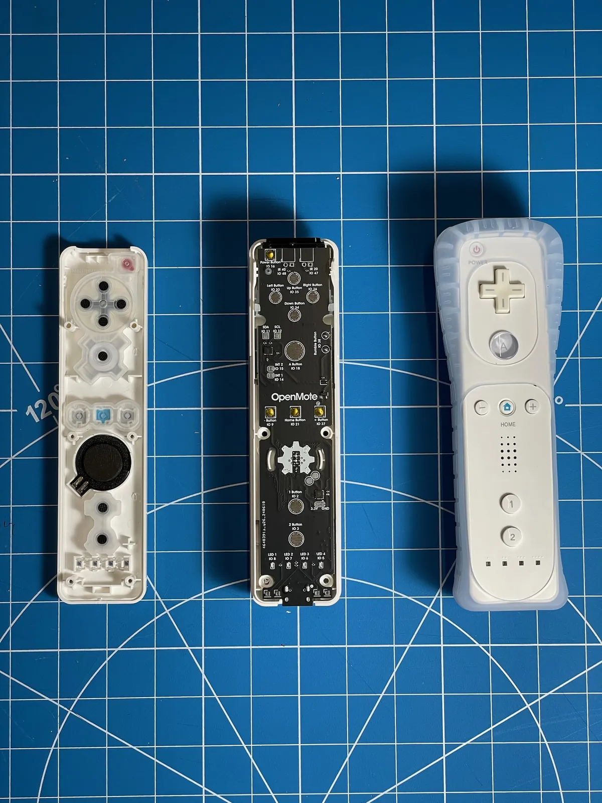
Three stages side by side on a cutting mat: an open Wii Remote shell with its rubber button pads, a black OpenMote board sitting in a white shell, and a finished remote
Tools
01
Tri-wing screwdriver (Y1)For the four battery-bay screws
02
Opening pickPlastic, not metal. Releases the shell clips
Parts
01
OpenMote boardReplaces the original board
02
B trigger bracketHolds the B button over the board
03
3D printed port coverFills the gap around the USB-C port
04
Rechargeable lithium batteryReplaces the two AA batteries
The Guide

Step by Step

Step1

Remove the Battery Cover
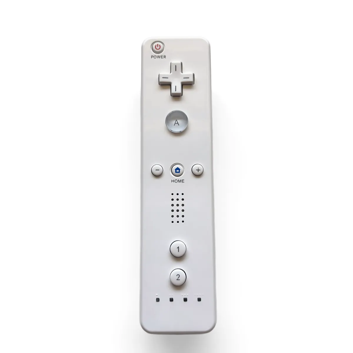
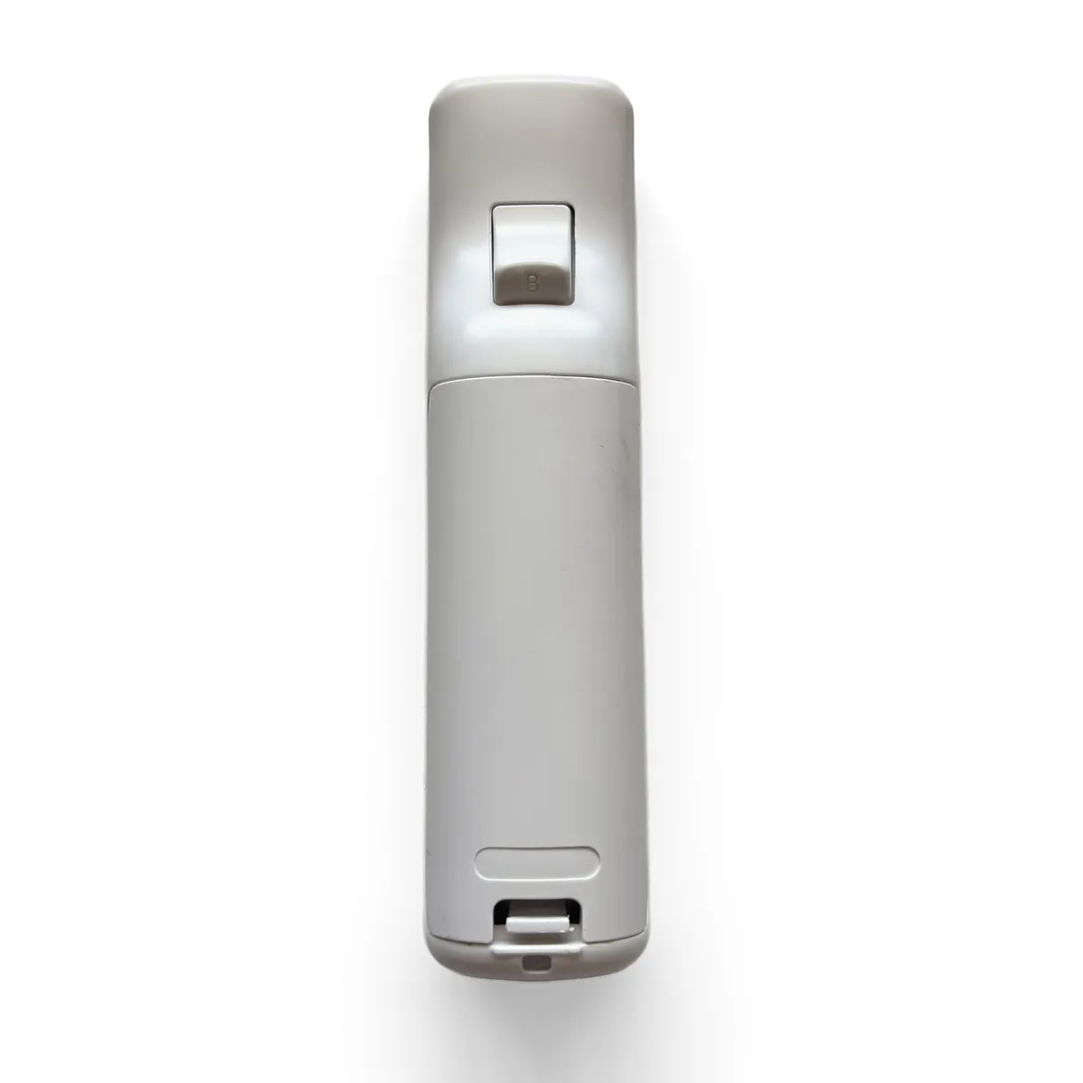
Wii Remote face down on the mat with the wrist strap removed, B trigger facing up
Thumb pressing the tab on the battery cover to slide it off
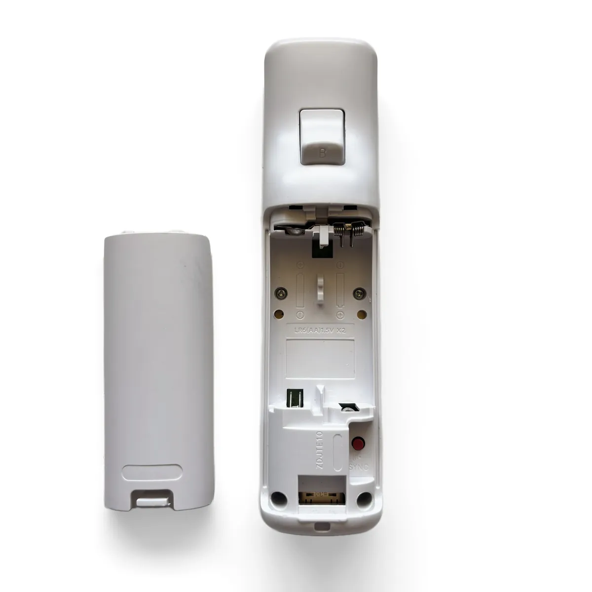
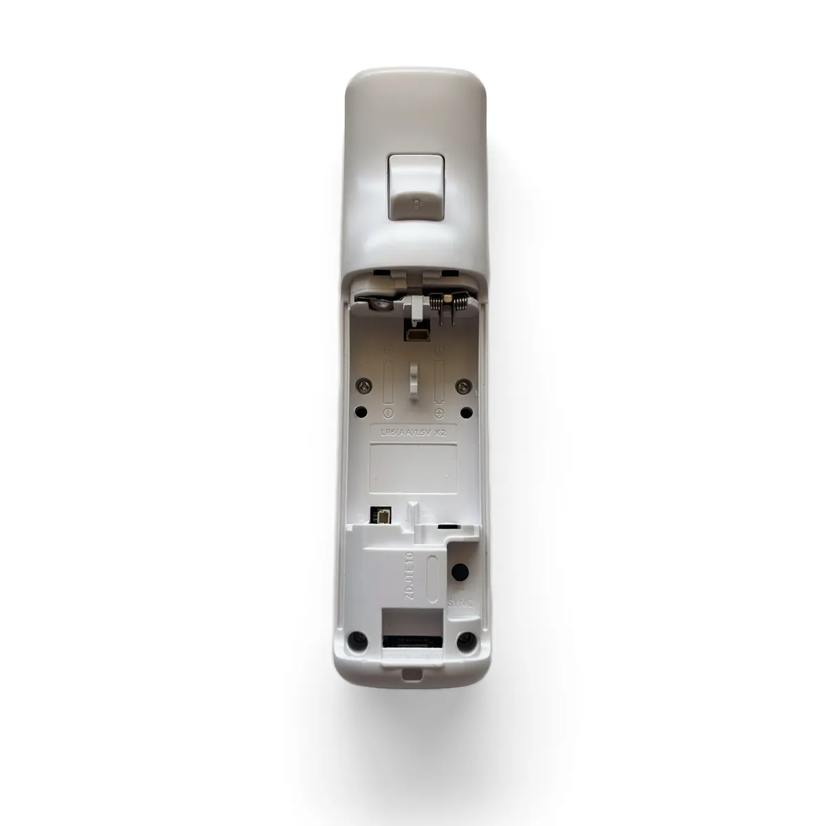
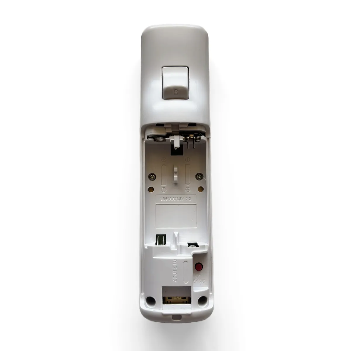
Battery cover off and the two AA batteries lifted out of the bay
  • Remove the wrist strap and any silicone jacket from the Wii Remote.
  • Flip the remote over so the B trigger faces up.
  • Press the tab at the bottom of the battery cover and slide it off.
  • Take out both AA batteries. The OpenMote runs on its own rechargeable cell, so you won’t need them again.
Step2

Remove the Tri-Wing Screws

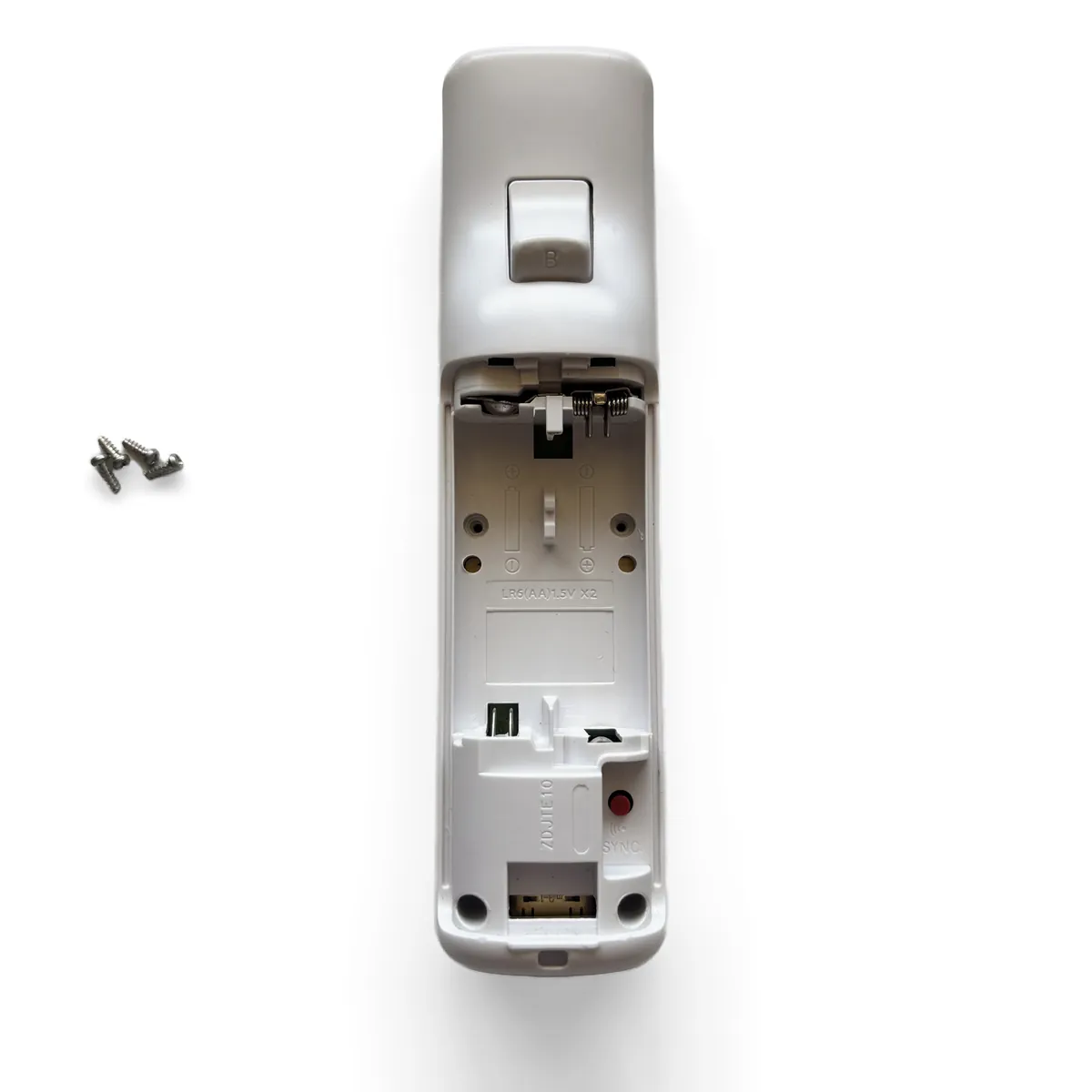
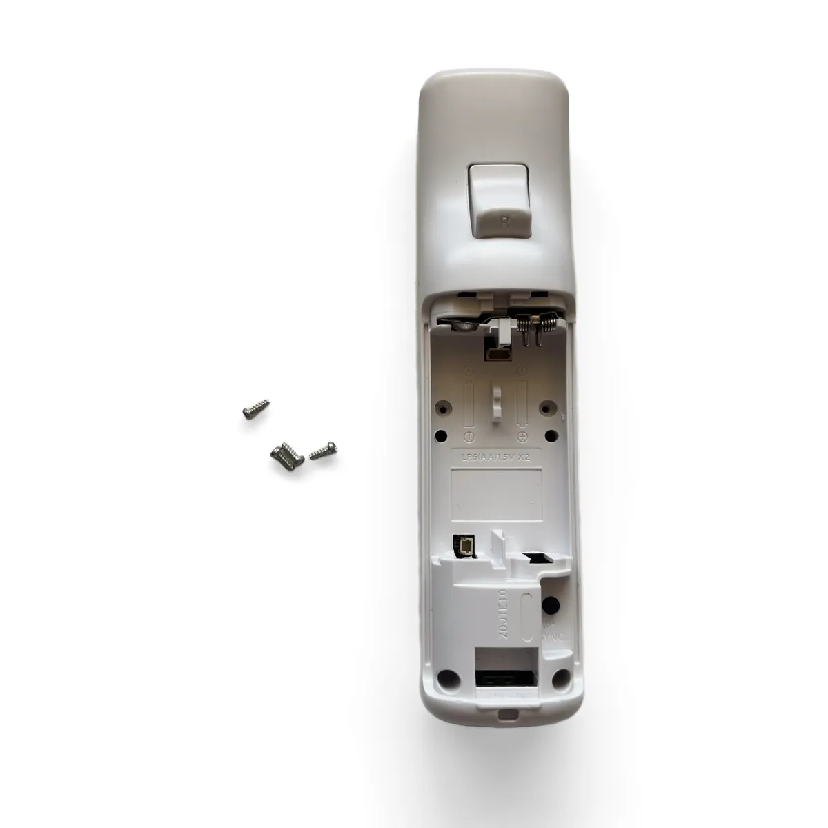
Open battery bay with the four tri-wing screws circled in red, two at the top and two at the bottom
Tri-wing screwdriver removing one of the screws inside the battery bay
  • Remove the four Y1 tri-wing screws inside the battery bay, two near the top, two at the bottom.
  • Note: Keep the screws together. You’ll reuse all four in Step 12.
Step3

Release the Shell Clips

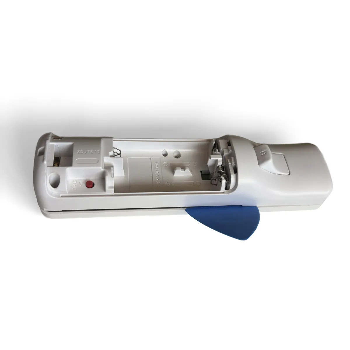
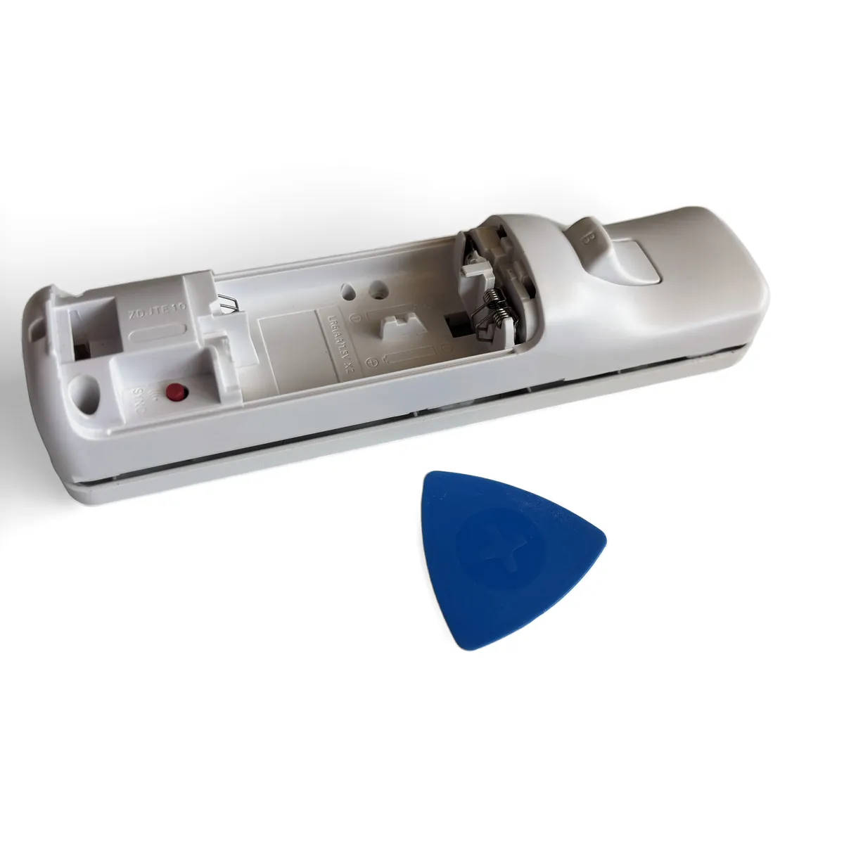
Blue opening pick pushed into the seam near the battery bay, with an arrow pointing along the seam toward the trigger end
Pick held upright in the seam while the other hand holds the remote
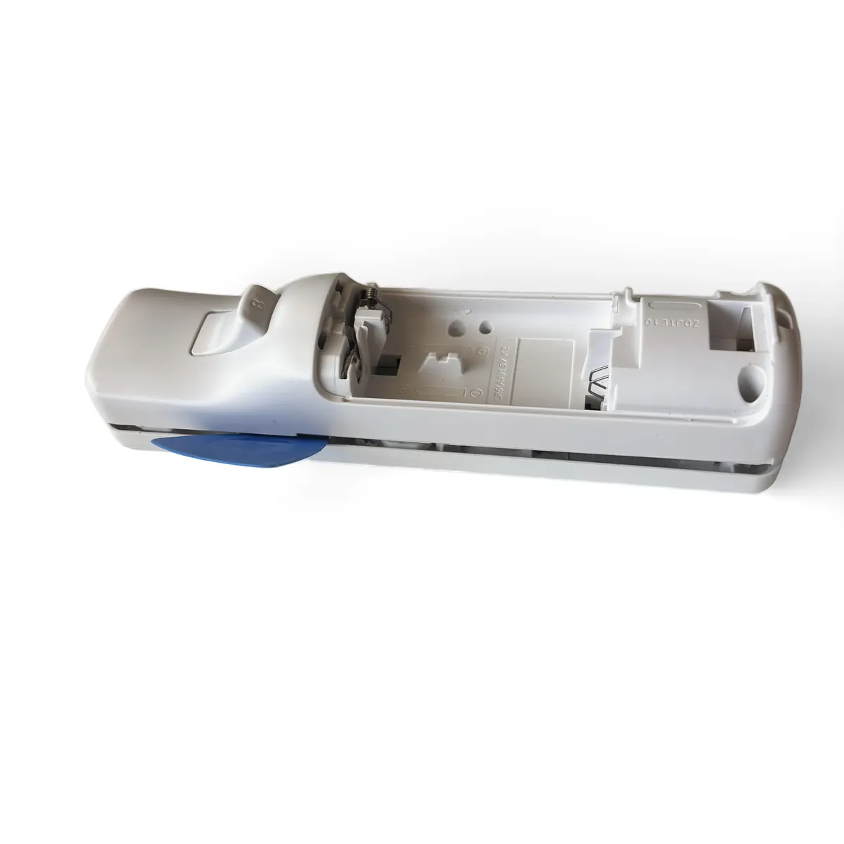
Pick sliding along the seam, the two shells starting to separate
  • Insert an opening pick into the seam between the top and bottom shells, near the battery bay.
  • Push the pick straight down into the seam, pointing toward the bottom shell. Don’t hold it flat or at an angle.
  • Note: Pointing the pick down pushes the clips apart instead of prying against them, so they release without breaking.
  • Slide the pick along the seam toward the trigger end, in the direction of the arrow, to release the clips. Work down one side, then the other.
  • Caution: Go slowly around the trigger. The clips there are short and can snap if you twist the pick.
Step4

Separate the Shells

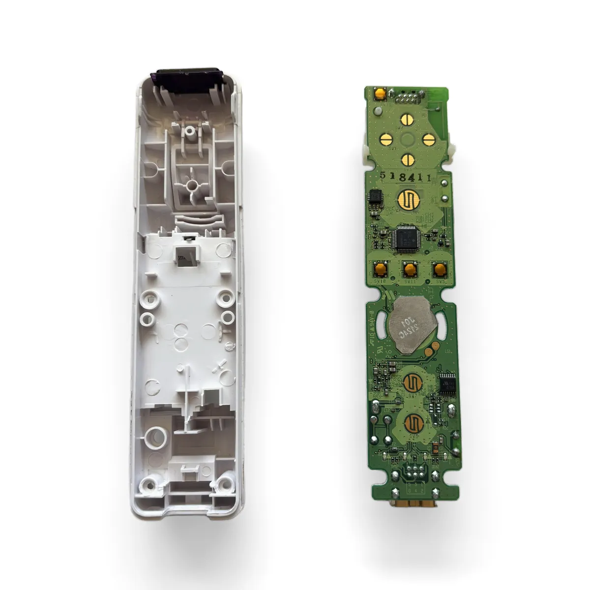
Top shell lifted away and set face down beside the bottom shell with the original board still seated
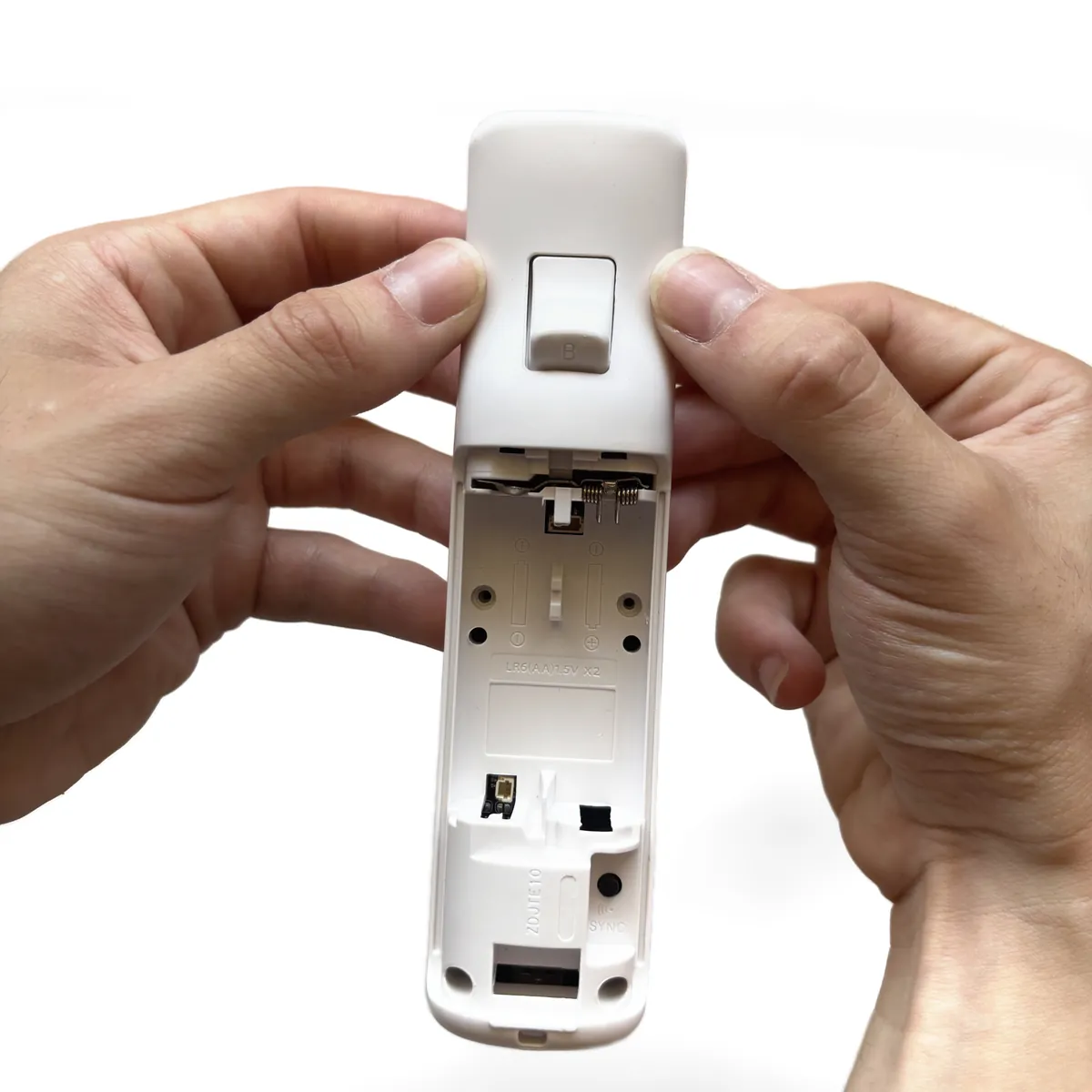
  • Lift the top shell straight up and set it face-down beside the bottom shell.
  • Caution: Keep the top shell’s button side facing the table as you lift it. If you flip it over, the loose buttons and membranes will fall out.
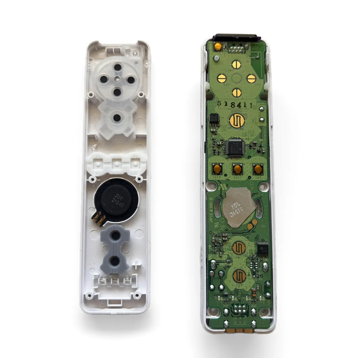
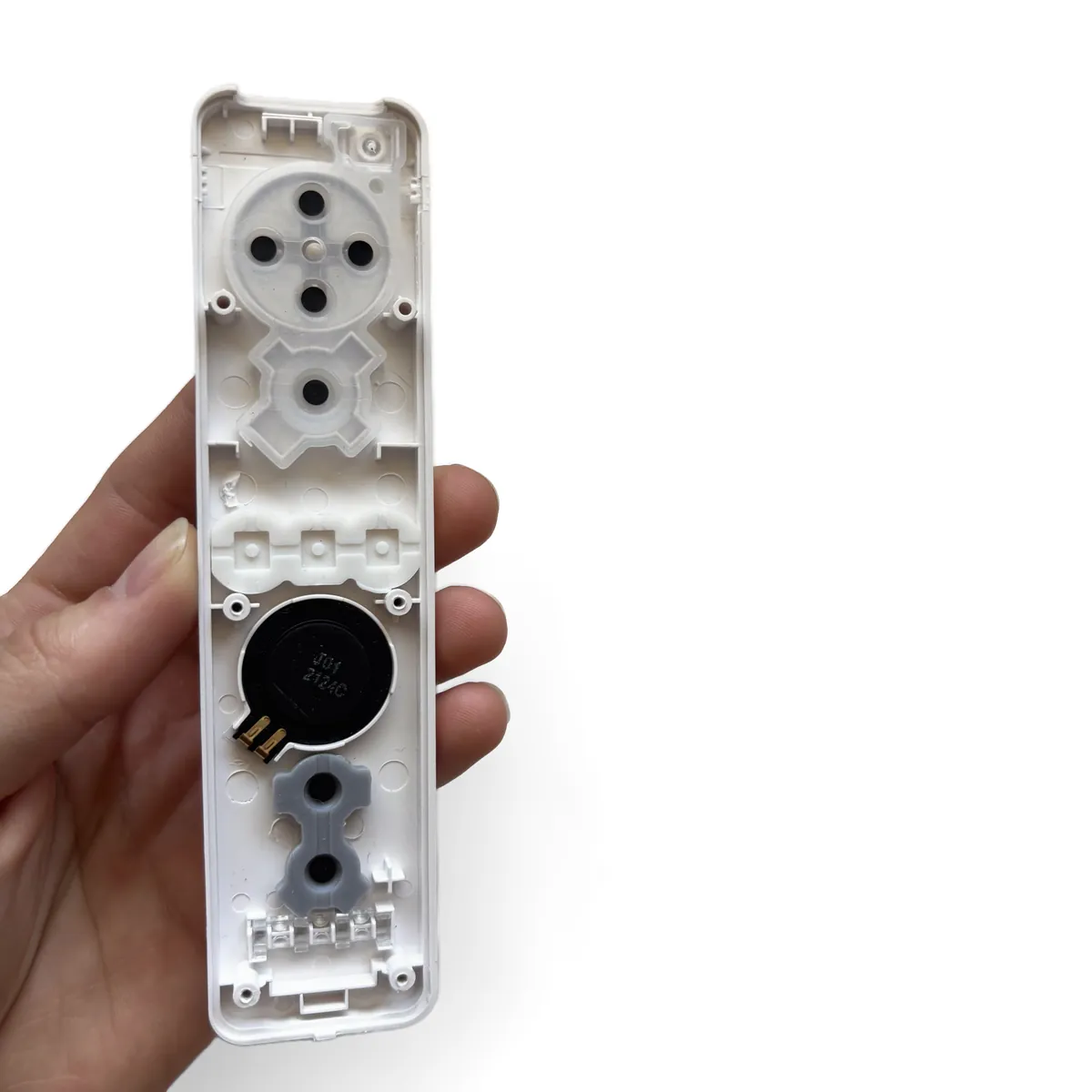
  • The original board stays seated in the bottom shell. The rubber button membranes and speaker stay in the top shell.
Step5

Lift Out the Original Board

Original Wii Remote board lifted out of the bottom shell by its edges, B trigger assembly attached underneath
  • Grip the board by its edges and lift it out of the bottom shell.
  • The B trigger assembly comes out attached to the underside of the board.
Step6

Check the Top Shell

Inside of the empty top shell showing the rubber button membranes and the speaker
  • Make sure every rubber button membrane is seated flat in the top shell.
  • Note: A membrane that has shifted will make its button feel mushy or not register at all.
Step7

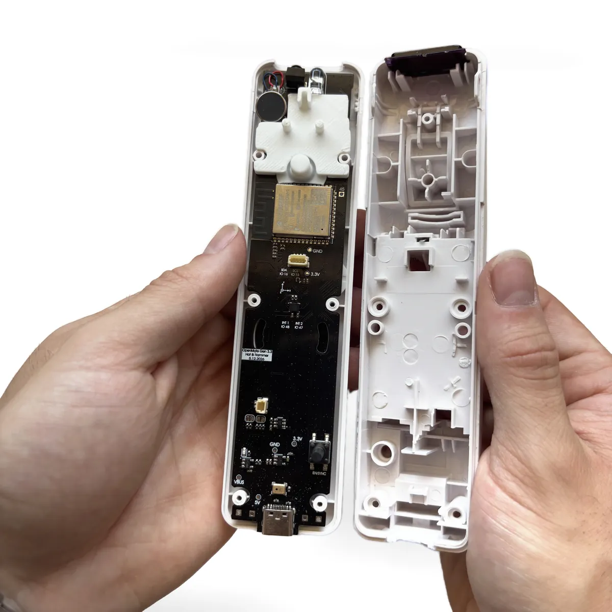
Seat the OpenMote Board

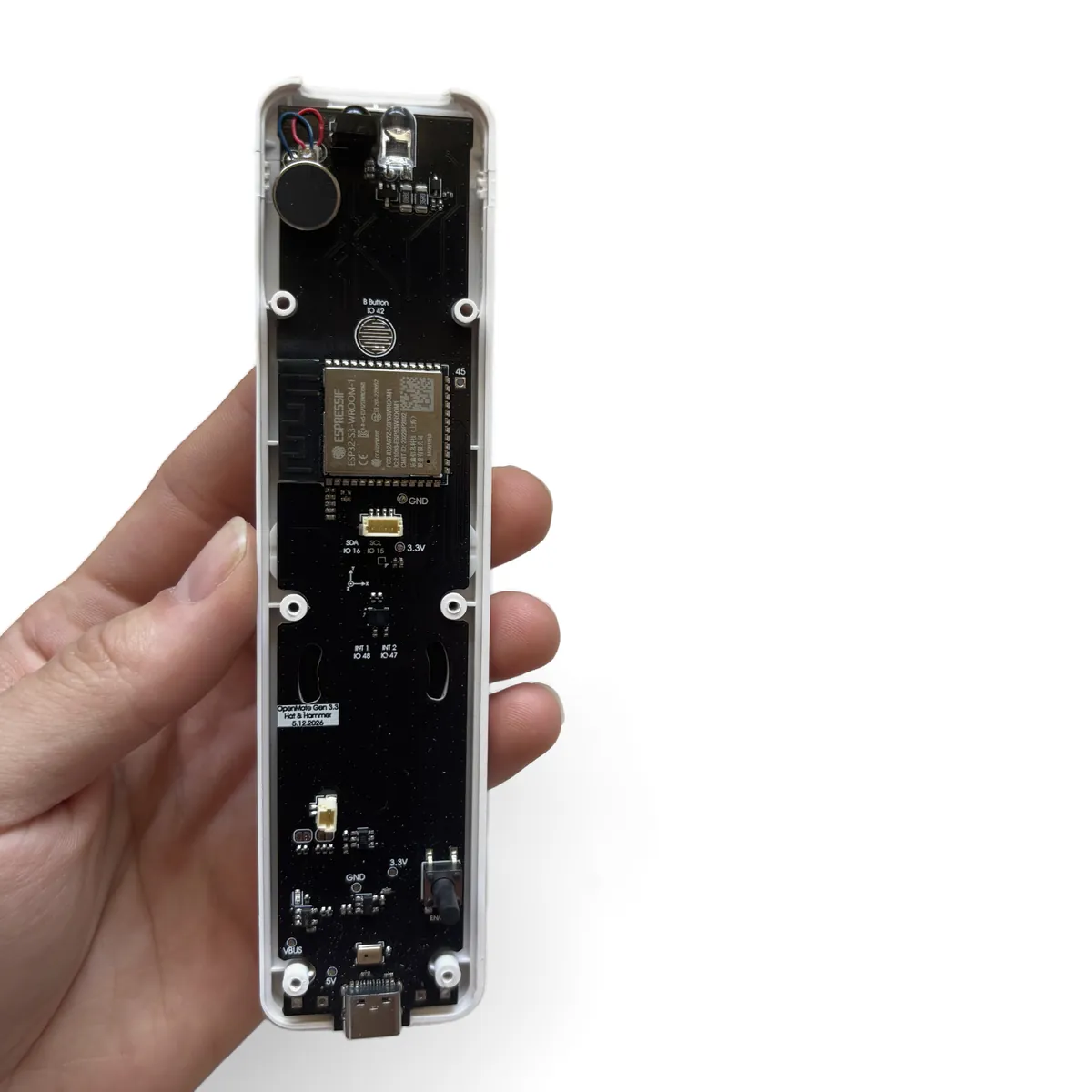
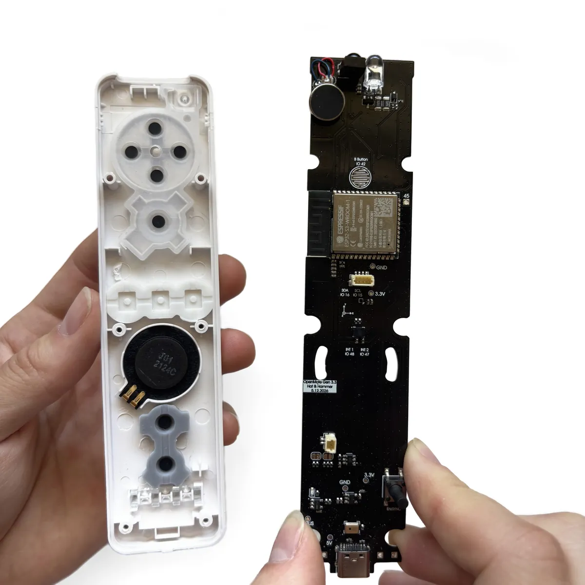
OpenMote board in the top shell with the six mounting holes circled in yellow over the shell posts
OpenMote board being lowered into the top shell, USB-C port at the bottom end
OpenMote board resting flat on the button membranes inside the top shell
  • Line up the OpenMote board with the top shell, USB-C port at the bottom end.
  • Lower the board in and press gently along its length until it sits flat on the membranes.
  • Alignment: Line up the six holes on the board with the posts in the shell, circled in yellow.
  • Note: The board should drop in without force. If it rocks, lift it out and re-check the membranes.
Step8

Fit the B Trigger Bracket

Bracket on the board with its two holes circled in yellow over the matching board holes
White B trigger bracket held above the top end of the board
Bracket pressed down flat over the top end of the board
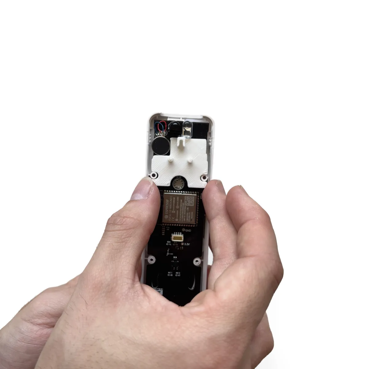
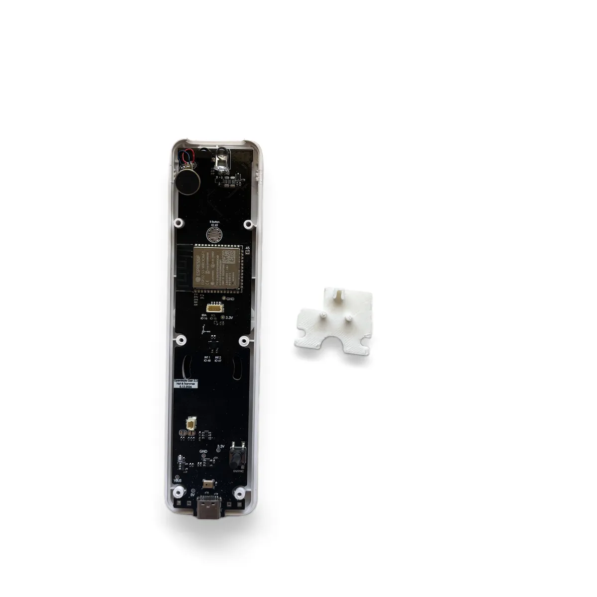
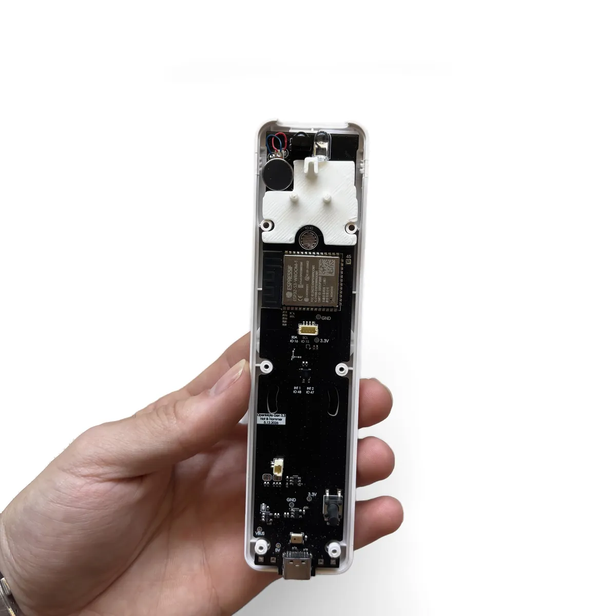
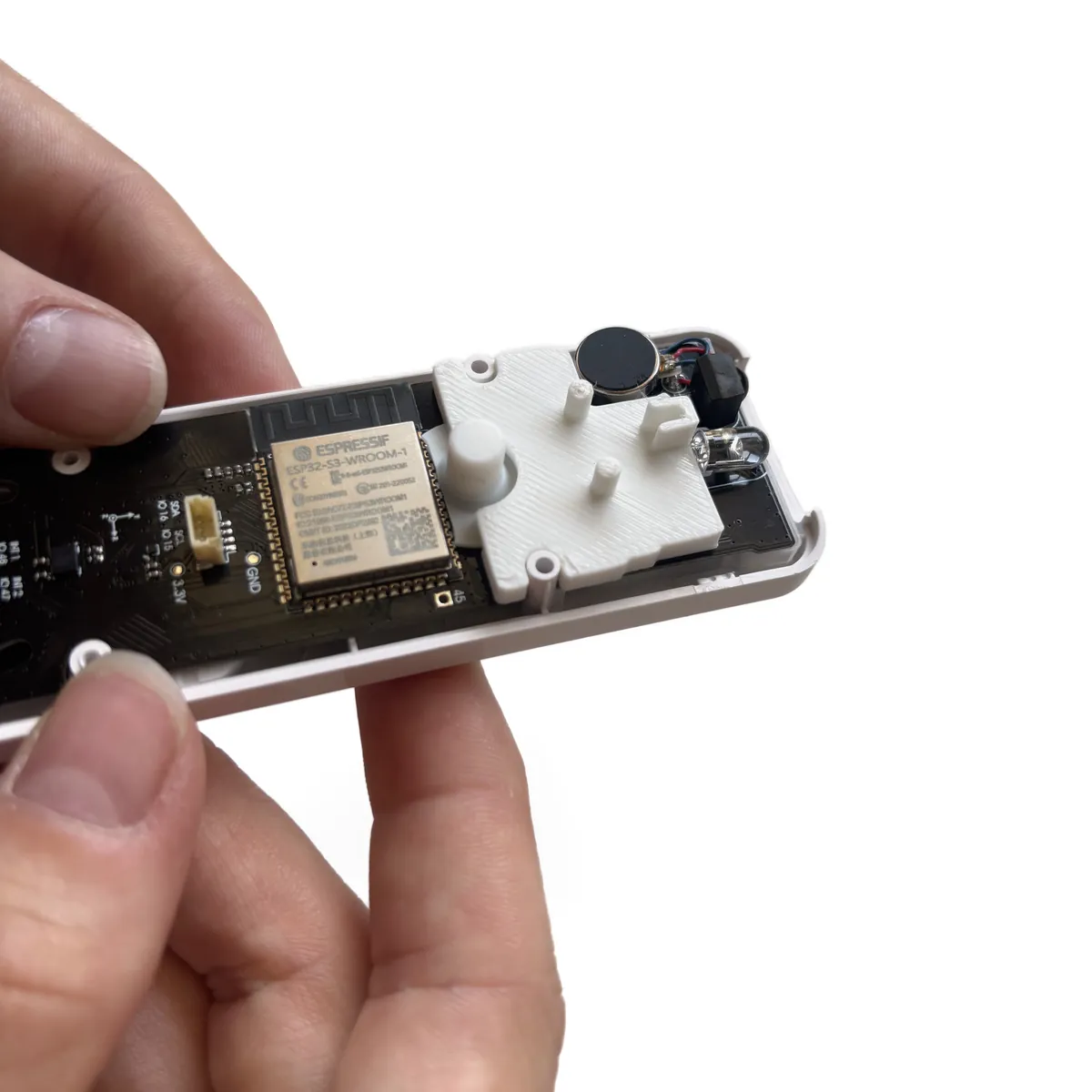
  • Take the white B trigger bracket from your kit.
  • Place it over the top end of the board, posts facing up, and press it down until it sits flat.
  • Alignment: Line up the two holes on the bracket with the two holes on the board, circled in yellow, before you press it down.
Step9

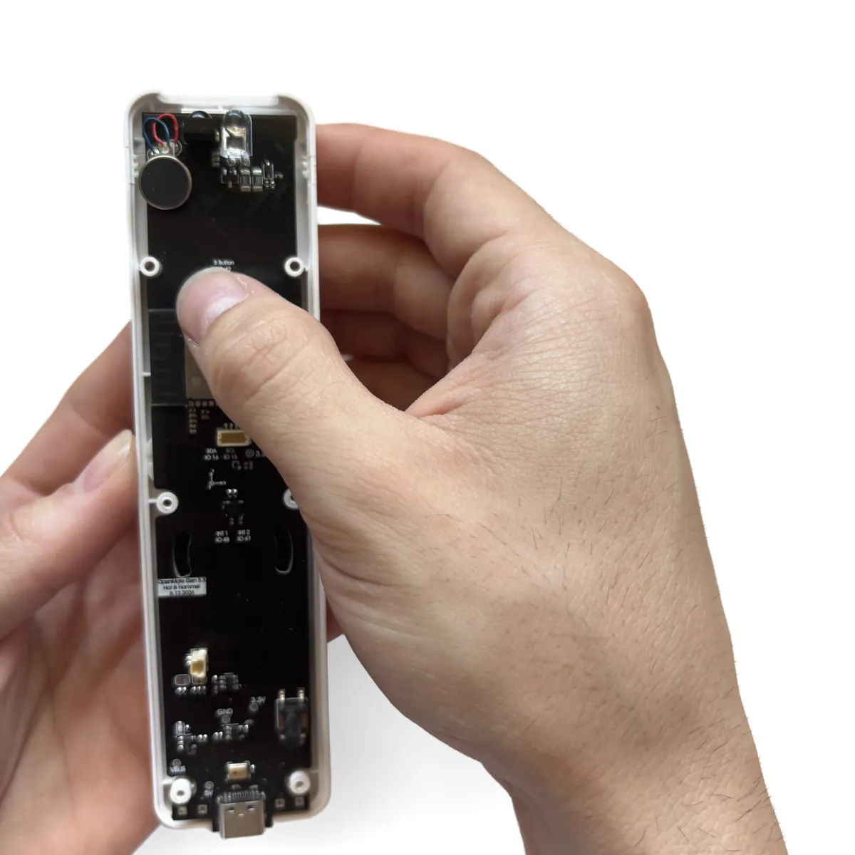
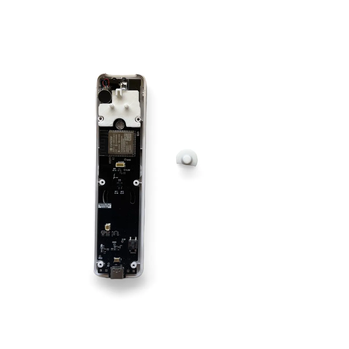
Install the B Button

B button held with the rounded face up and the half-moon tab pointing toward the ESP32 chip
B button dropped into the round opening on the bracket, sitting flush
  • Hold the B button with the rounded button face pointing up, away from the board.
  • Turn it so the half-moon flange points toward the ESP32 chip, away from the trigger end of the remote.
  • Drop it into the round opening on the bracket so it sits flush.
Step10

Insert the 3D Printed Port Cover

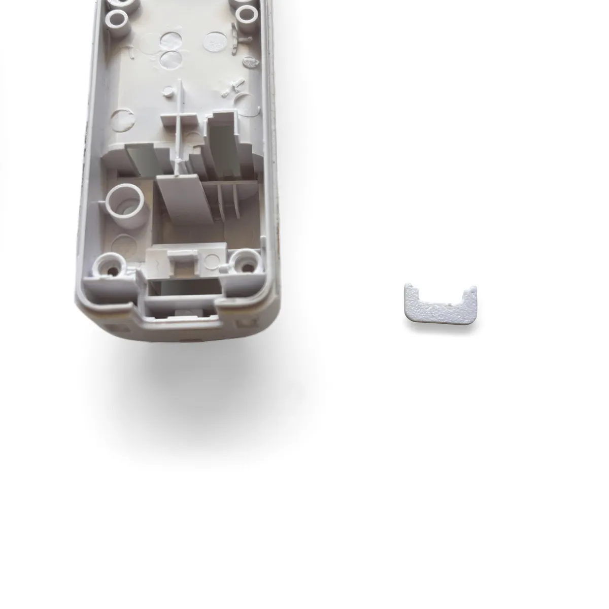
Small 3D printed port cover held next to the opening at the bottom end of the bottom shell
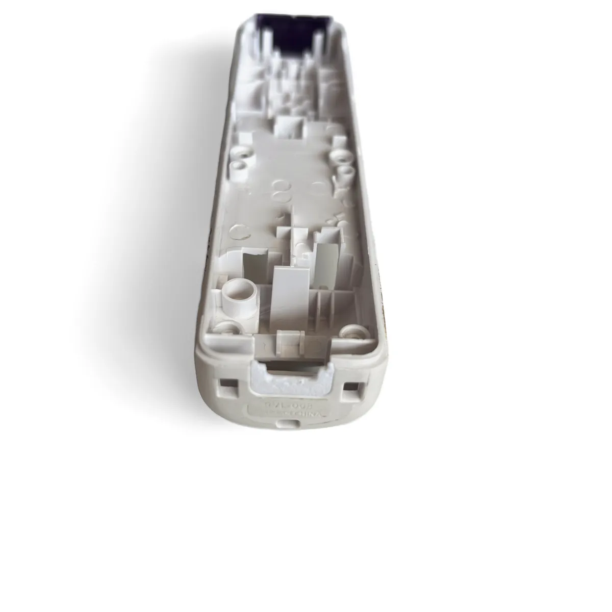
Bottom shell end with the port cover in place, the gap around the USB-C port filled
  • Take the 3D printed port cover and press it into the opening at the bottom end of the bottom shell.
  • The cover fills the gap around the USB-C port so the end of the remote looks clean.
  • Note: No printer? Download the STL and order it from any print service.
  • Download the port cover STL
Step11

Close the Shell

Bottom shell lowered onto the top shell with the reset button hole circled in yellow and a line to the reset button on the board
Shells brought together starting at the trigger end
Thumbs squeezing the shells shut at the top end, one clip at a time
Seam closed along one side of the remote
Closed remote with the seam flush all the way around
  • Lower the bottom shell onto the top shell, starting at the trigger end.
  • Check that the B button is seated on top of its membrane button before you close the shell.
  • Alignment: The reset button on the board fits through the round hole in the bottom shell, circled in yellow. Line them up as you close the shell.
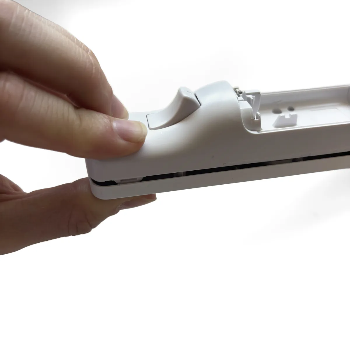
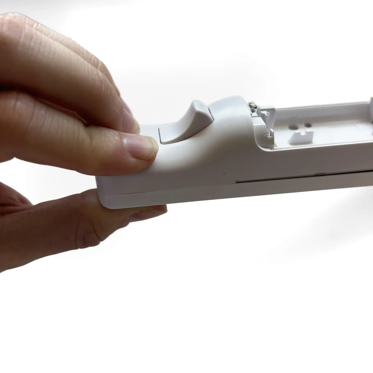
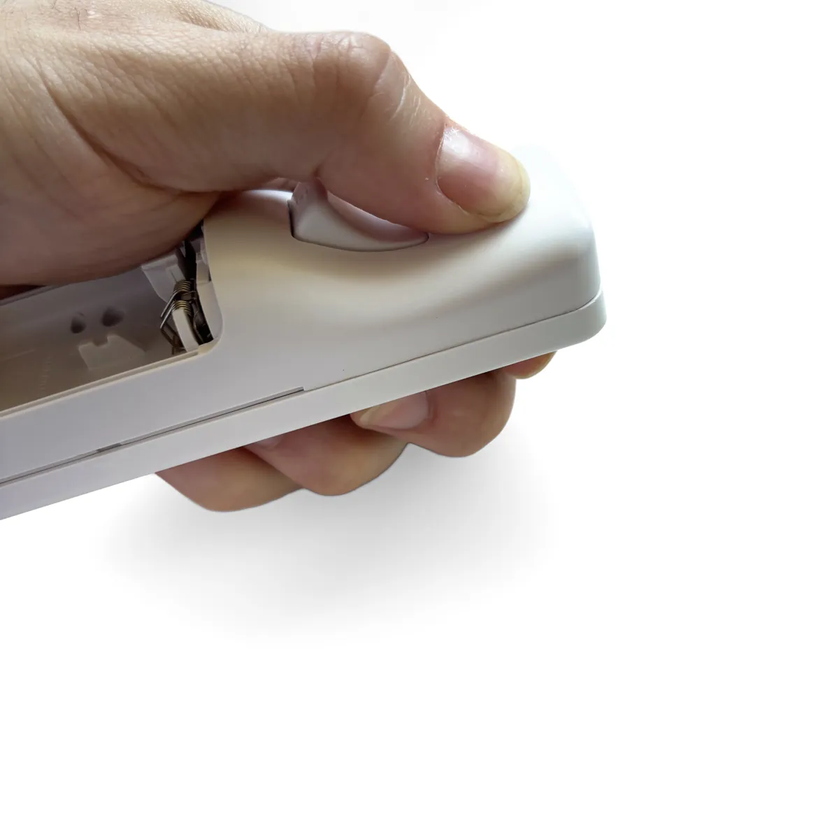
  • Squeeze the top of the remote where the two clips are, one clip at a time, until each one snaps shut.
  • Caution: Don’t force it. If the seam won’t close, open the shell and check the bracket and B button are seated.
Step12

Reinstall the Screws

Reassembled remote face down with the four screw holes circled in red and the screws beside it
Screwdriver reinstalling one of the four tri-wing screws, holes circled in red
  • Reinstall the four tri-wing screws you removed in Step 2, in the locations circled.
  • Caution: Stop as soon as each screw is snug. Overtightening can strip the plastic posts.
Step13

Connect the Battery

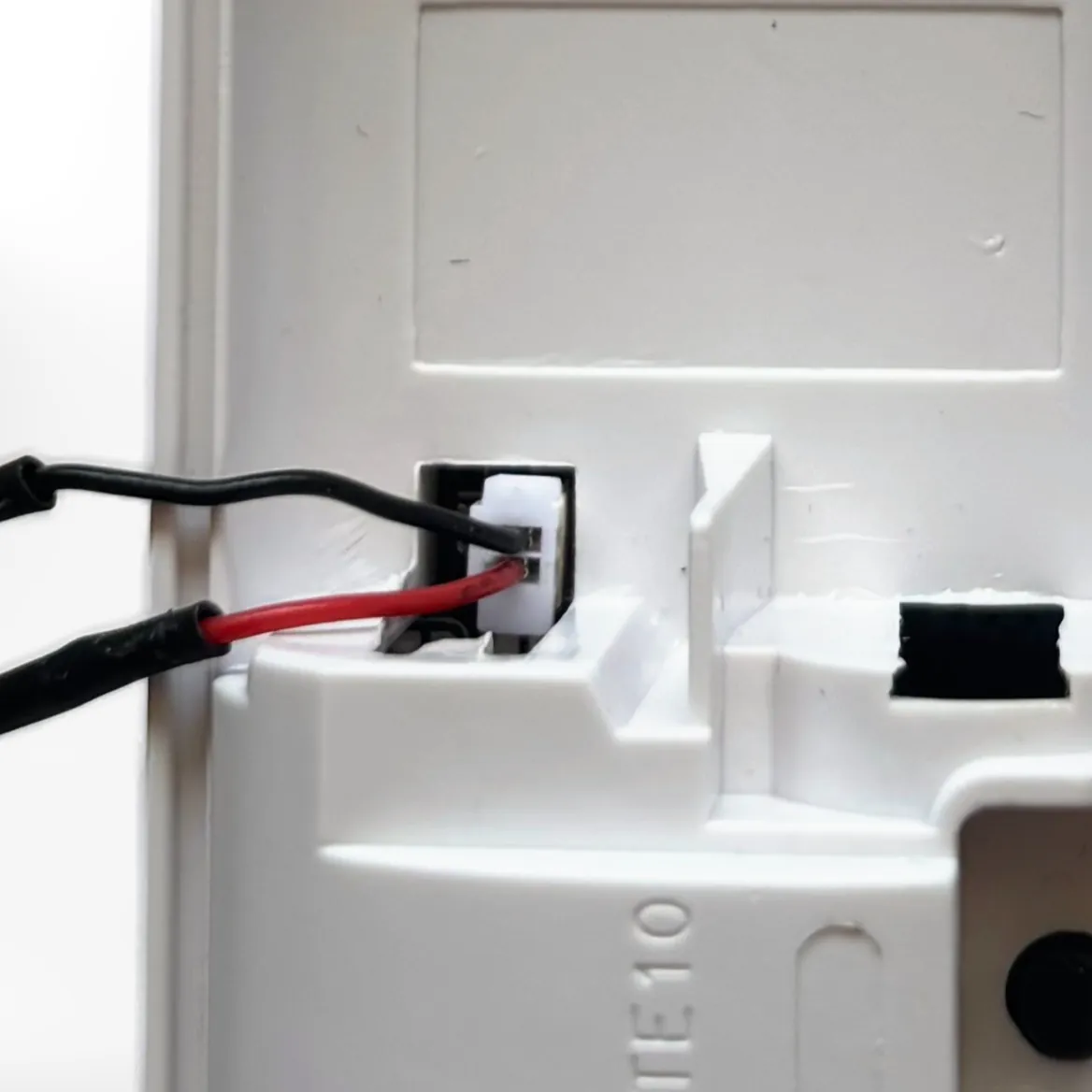
Close-up of the battery socket. The black negative wire goes in the top pin, marked Negative, and the red positive wire in the bottom pin, marked PositiveNegative −Positive +
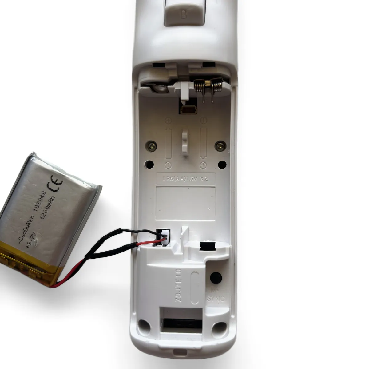
Battery connector being plugged into the socket at the bottom of the battery bay, with Negative on top and Positive below marked by arrowsNegative −Positive +
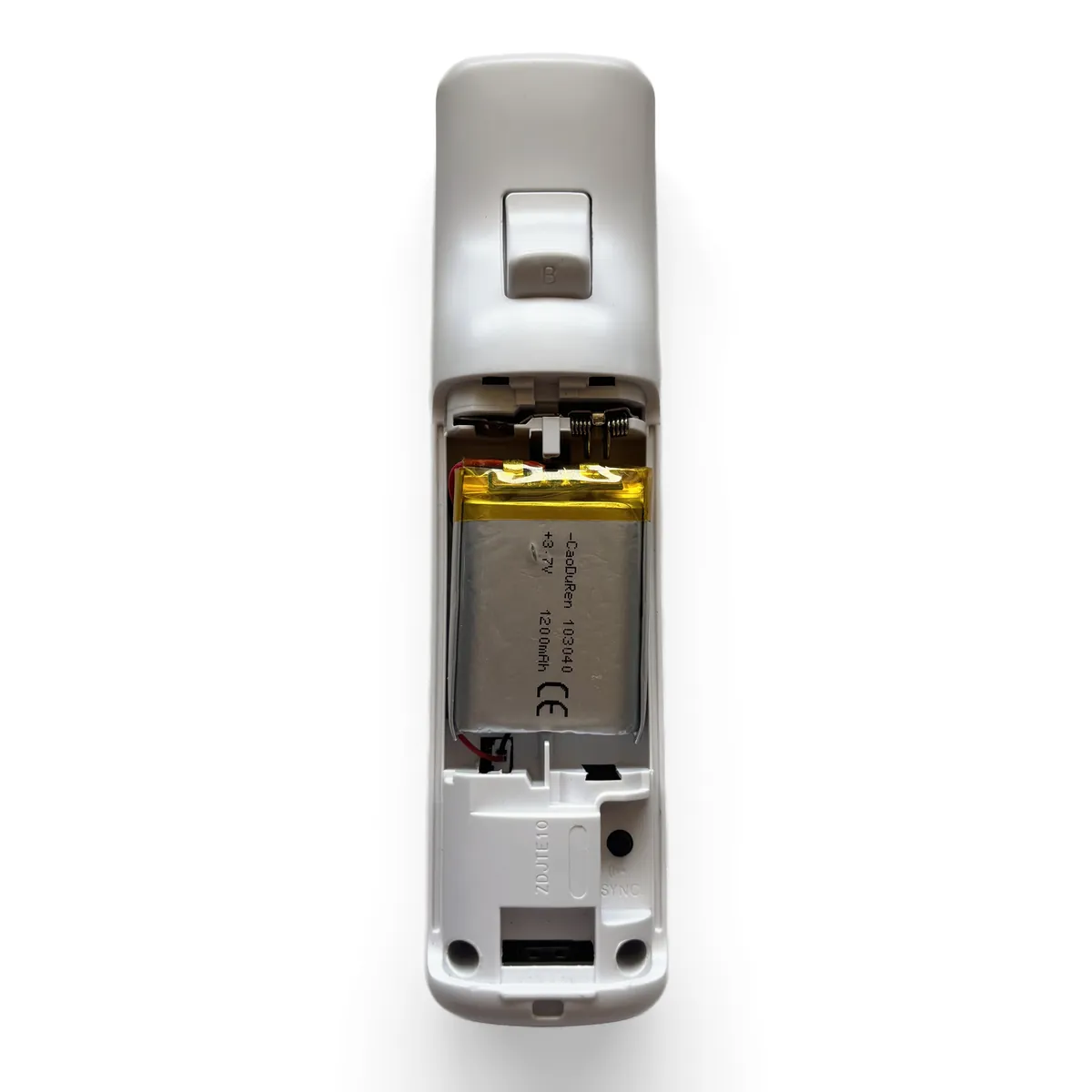
Battery set into the bay with the wires tucked to the side
  • Plug the battery connector into the socket at the bottom of the battery bay.
  • Negative (black wire) goes on top. Positive (red wire) goes on the bottom.
  • Caution: Don’t install the battery backwards. Match the wires to the Negative and Positive labels in the photo before you plug it in. Backwards will damage the board.
  • Tuck the wires to the side and set the battery into the bay.
  • Caution: Never puncture, bend or crush a lithium battery.
Step14

Replace the Battery Cover

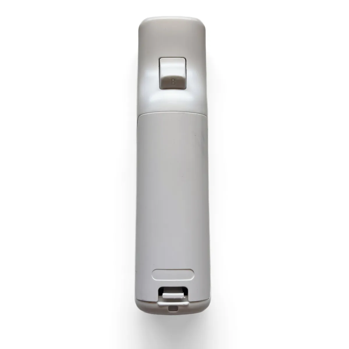
Battery cover sliding back on
Finished remote, back side up, with the battery cover clicked shut
  • Slide the battery cover back on until it clicks.
  • Your OpenMote is ready. Charge it over USB-C before first use.
Conclusion

Done. Your OpenMote is in.

Nice work. Charge it over USB-C before first use. Setup and programming guides are next. Until they are up, ask in the Discord.

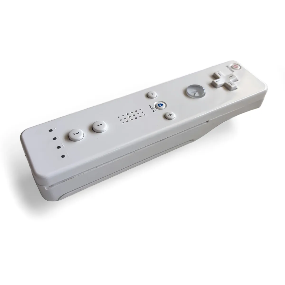
A closed Wii Remote with OpenMote inside, button side up. From the outside it looks like the original.
You were partway through.Resume